Roland GA-112 Chassis replacement
I purchased a Roland GA-112 amp on eBay and it arrived with the chassis cracked on the right side. So I called Roland for a replacement side and they shipped me a new chassis, as its glued together into one piece! So after forgiving the cheat on eBay who sold me the cracked chassis while posting pictures of a pristine amp, I also forgave Roland for a poor design of the chassis – and not thinking of design for serviceability. 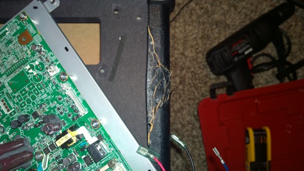
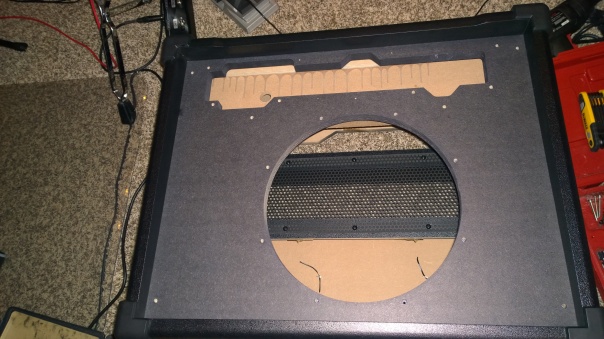
Above is the cracked right side of the chassis. If it had been designed as a replaceable part, it would be a matter of removing a few screws and taking it off, putting on the new one.
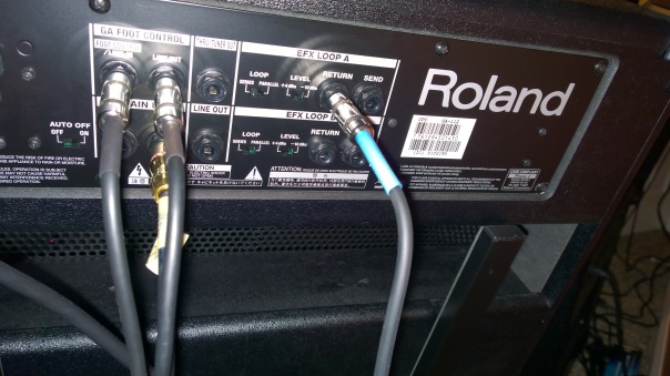
I started by taking a picture of the back of the GA-112 amp as I use two of these in my studio for left/right channels coming from my Roland VG-99 guitar synth. Basically, the outputs from there use the amps as just power amped cabinets, bypassing the front input which drives the amp circuit.
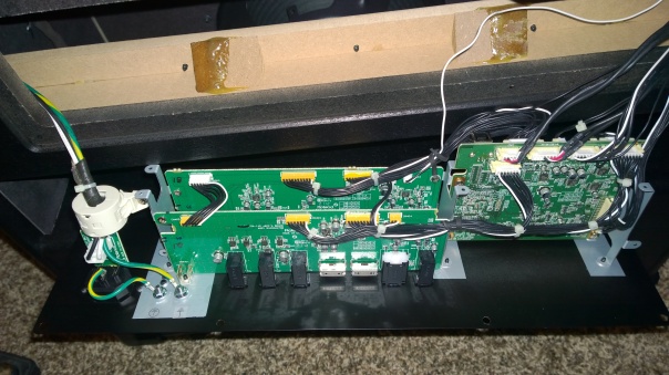
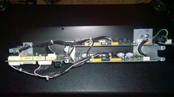
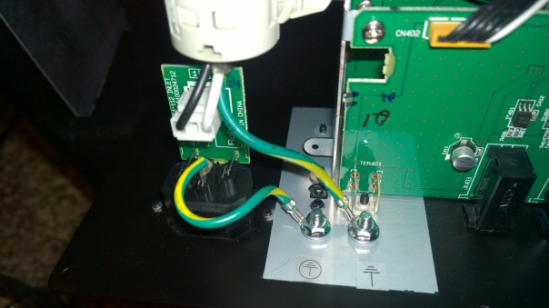
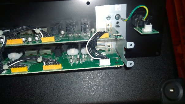
Above is the back removed from the amp chassis. Eight things have to be unwired to detach the entire board assembly completely. The plug on the left with the black and white wires, the nut holding the earthing wire, the three plugs on the upper right, starting from the two with red wires and the one immediately next to it (but not the last one on the right corner), as well as the small plug underneath the board on the upper right, which is seen between the second and third plugs, as well as one small plug with black and white wires in the middle of the lower board on the left. Also, remove the screw holding the cylindrical ceramic part around the power cable to the left.
After removing the screws for the front grill, remove the front orange cosmetic panel unscrewed using a matching allen key. Then remove the three retaining screws that hold the front amp circuit board in place.
Keep the amp upright and unscrew the eight speaker screws, reach in from the back of the amp and while holding the metal rim of the speaker firmly from the front, push the coil center gently with hand. The speaker will dislodge and drop out. Do not let it fall as it will land on the power amp at the bottom of the chassis!
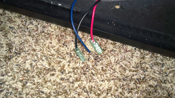
Unclip the three leads from the back of the speaker. Note that blue one goes on top not the black one, when you reassemble.
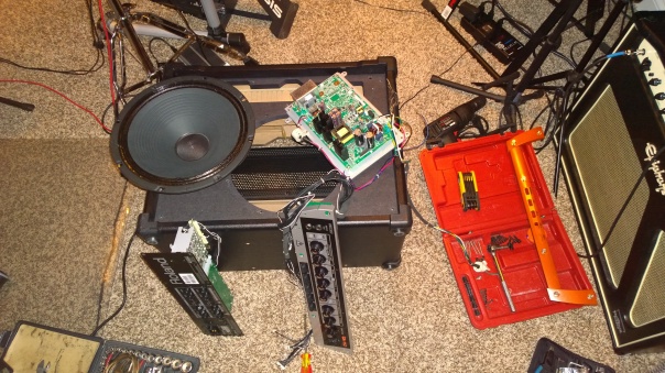
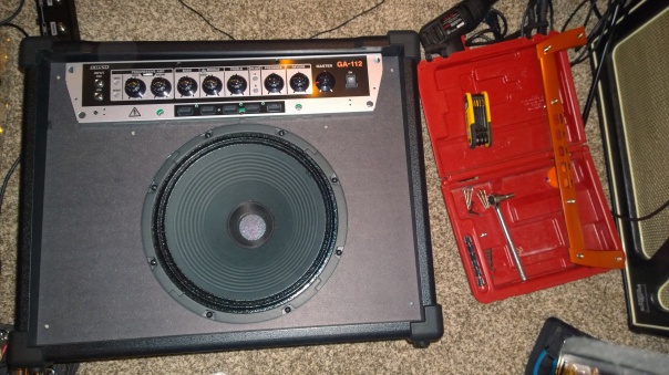
Above on the right is the set of all disassembled screws and one flanged nut kept in batches – do not mix them or your reassembly time will be longer! Once the speaker, front and back panels are out, flip the amp over and unscrew the four screws to remove the power amp from the bottom of the chassis.
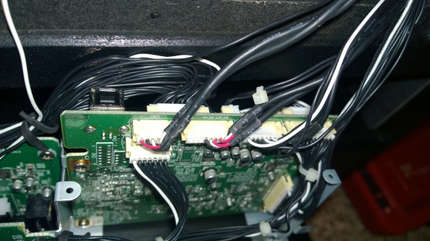
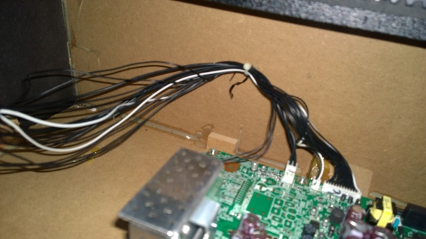
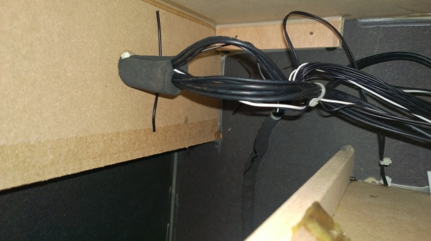
Make sure to untwist and retwist the black cable tie on the upper left of above photo after reattaching the plugs when rewiring the board after placing it into the new chassis.
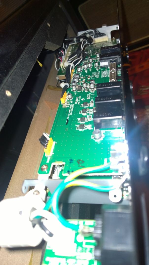
Check out the USB port present on the mid-left! This is on the rear panel, and since its too far back from the rear panel, there is no hole in it to allow connecting to it from outside. I bet this allows USB recording at 44.1KHz/24-bit or reprogramming of the amp COSM models. The manual does not mention it!
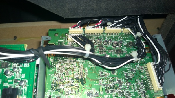
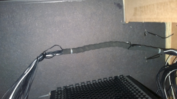
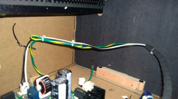
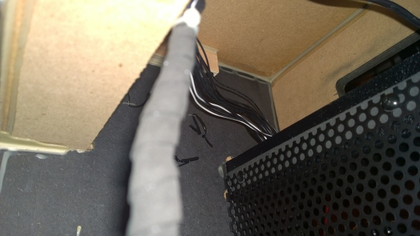
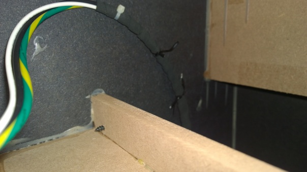
Make sure to keep cables clear of the boards by using the twist ties stapled on the inside of the chassis on both sides of the interior. This will prevent hum by keeping all cables close together and also prevent cables being subjected to conductive heating from the components on the board.
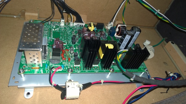
Power amp remounted on bottom of chassis. Four screws have to secure it from underneath. This is the high voltage components, and it is crucial to keep cables tied off using twisties onto the side of the chassis.
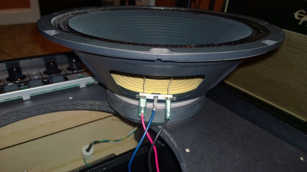
Reconnect the speaker using its wires as shown above: blue goes in the middle.
Reconnect the white plug and earthing wire with the nut.
Reconnect the power amp plugs back and tie off cables to chassis using stapled twisties inside.
Insert and screw front and back panels and mount the speaker, screw it back into chassis.
Secure cables using twisties to inside of chassis
Posted on February 26, 2016, in Guitar gear review, Guitar rig hookup options and tagged Roland GA-112 teardown. Bookmark the permalink. Leave a comment.

Leave a comment
Comments 0